Back to Sample Jobs
This output pack was generated from a 39-minute raw field transcript.
View Raw Transcript →
Sample document. All company names, site details, personnel and observations are fictional. This illustrates the structure and content of a real AI Site Rep output pack.
AI Site Rep — Design Capture Assistant  ·  Output Pack
Pump Station 4 — Modification Scope Walkthrough
Jupiter Processing Facility  ·  Kalgoorlie WA
Pinnacle Industrial Services
D. Hartley
14 May 2026
Draft — Pending review
AI Capture Session

Capture Session Metadata

Session started
09:14 AWST — 14 May 2026
Duration
47 min 23 sec
Location
Jupiter Processing Facility, Pump Station 4
Capture mode
Audio + Visual (continuous)
Photos captured
6
Transcript length
~4,800 words
Pack generated
14 May 2026, 10:08 AWST

TRANSCRIPT EXCERPT — 09:31:14 AWST

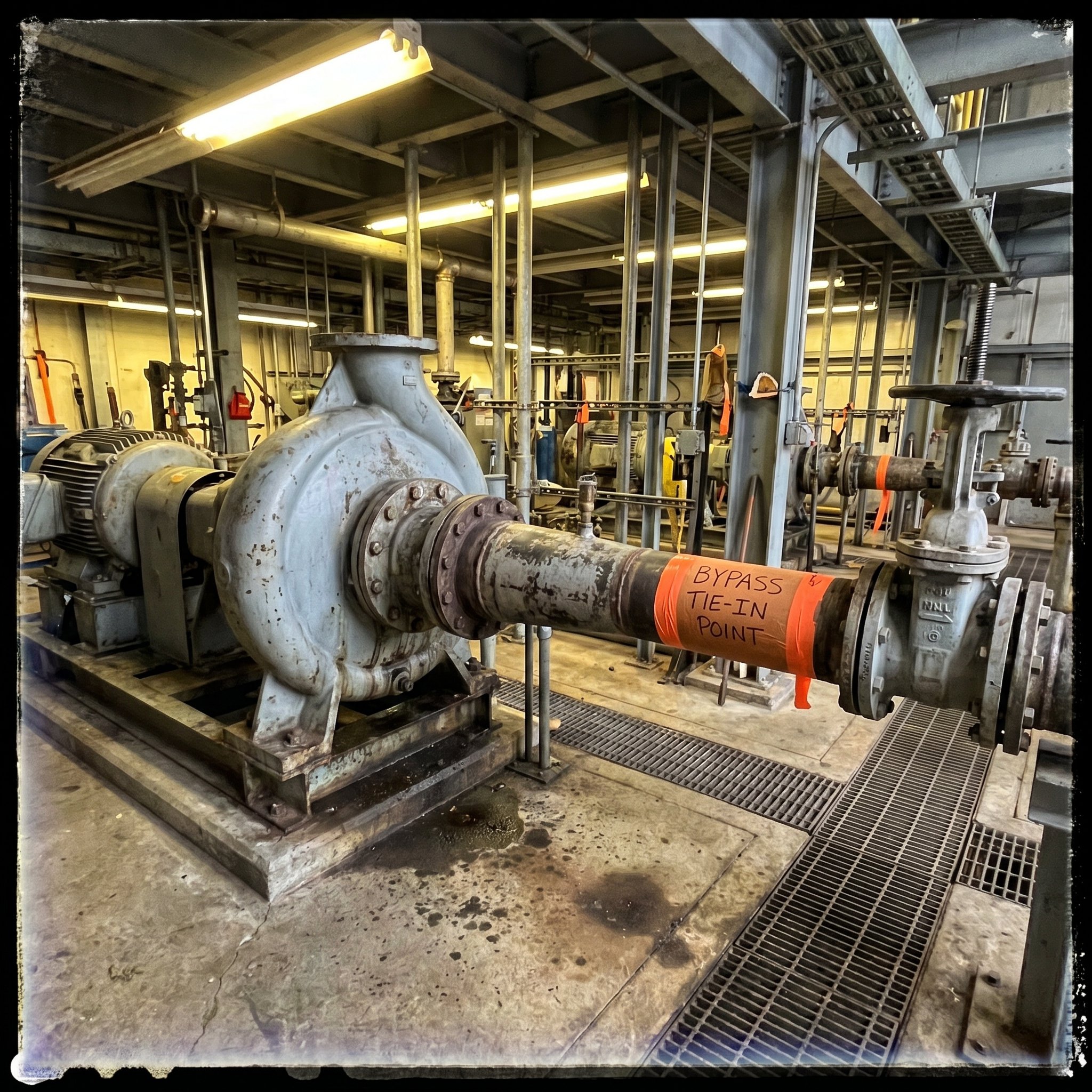
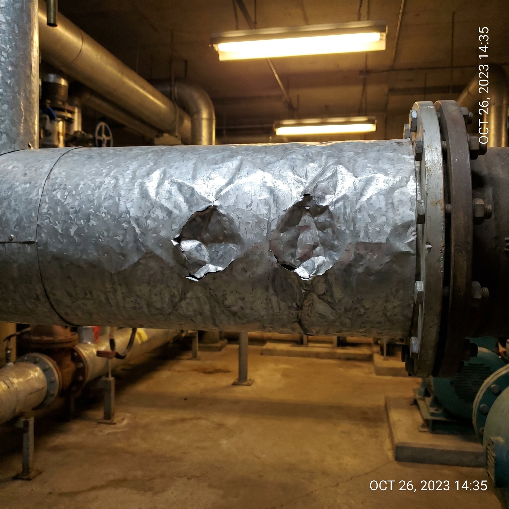
“…okay so this is the discharge side, you can see the four-inch flanged outlet here, the isolation valve — that’s a gate valve, manual — is in good condition, no visible corrosion, the spectacle blind — I don’t see one here Tom, is that correct — yeah no blind on this one — okay no spectacle blind observed, and then coming down the rack here the insulation, see that section there, that’s got some damage, I’d say about 300 mil from the flange, worth noting for the scope, we’ll need to call that out, probably add an allowance — yeah at least a metre either side to be safe — agreed, I’ll flag it…”

This excerpt is approximately 45 seconds of captured field conversation. The full 47-minute session is indexed and searchable.

1
Inspection Summary

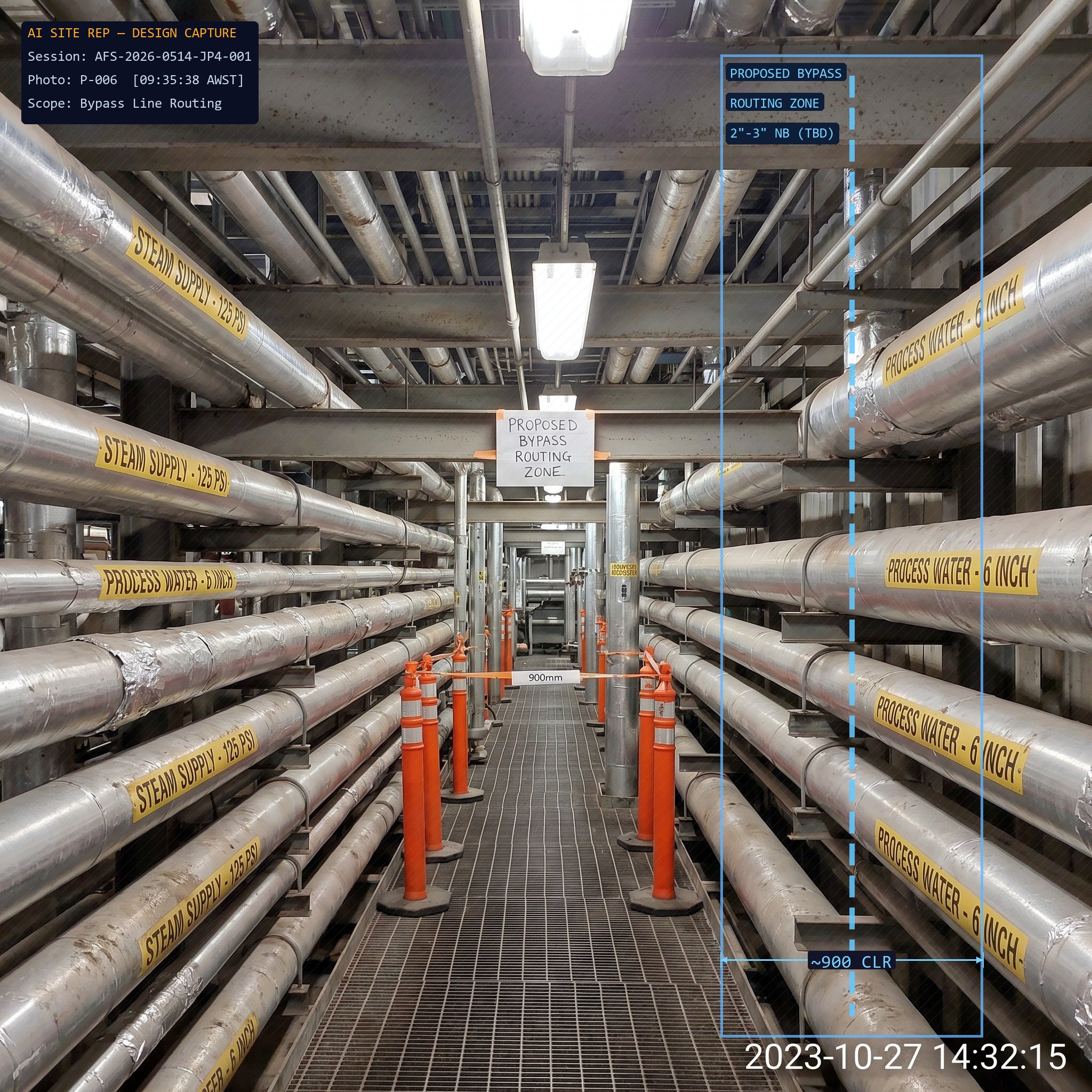
Site walkthrough conducted at Jupiter Processing Facility, Pump Station 4. The purpose of the visit was to scope a proposed modification to the existing pump discharge configuration to accommodate an additional bypass line requested by the client. The walkthrough ran approximately 45 minutes with client representative T. Nguyen (Mechanical Lead) present. Three areas were inspected: the pump skid, the discharge manifold, and the pipe rack access corridor. Existing drawings (Rev C) were referenced on site but noted as potentially out of date against the as-installed configuration. Photos captured throughout. Audio and observations recorded continuously from arrival at the pump skid.

2
Existing Condition Summary
Pump model
Grundfos NK 100-250 (noted on nameplate — confirm against CMMS)
Discharge configuration
4" flanged discharge to header. No existing bypass provision. Isolation valve (gate, manual) in good condition. No spectacle blind observed.
Pipe rack access
Approximately 900mm clear between existing services at the proposed bypass routing. Rack loading capacity unknown — client to confirm with structural.
Insulation
Discharge line insulated to approximately 600mm from pump flange. Condition fair — surface damage at two points, non-critical. Photo refs P-003, P-004.
Existing drawings
P&ID Rev C on site. Pump discharge shown without bypass. As-installed configuration appears to differ at the manifold tee — drawing may not reflect recent minor works. Confirm with client document control.
General condition
Equipment in operational service. No significant corrosion observed. Area clean and accessible. HSE: confined space not required for proposed scope.
3
Defect & Finding Summary
Insulation damage — discharge line. Surface damage at two locations approximately 300mm and 550mm from pump flange. Not structural. Recommend repair prior to any hydro test to avoid water ingress under existing cladding. Photo refs P-003, P-004.
Drawing discrepancy — manifold tee. As-installed configuration does not match P&ID Rev C at the discharge manifold tee. Minor works appear to have been performed. Client to confirm revision status and provide updated drawing before design commences.
Rack loading capacity unknown. Proposed bypass routing requires attachment to existing pipe rack. Structural capacity not confirmed. Engineering to review before routing is finalised. Flagged as a design constraint.
Access corridor — clear. 900mm clearance observed between existing services at proposed routing. Sufficient for proposed 2" bypass line. No obstruction issues at this stage.
4
Client Requirements Captured
Bypass line size: 2" minimum. Client prefers 3" if routing and rack loading permit.
Valve type: Client requests ball valve on bypass for faster isolation. No preference on actuation — manual acceptable for this service.
Tie-in point: Preferred tie-in downstream of existing isolation valve. Client flagged this verbally — confirm in writing.
Shutdown window: Client has a planned shutdown in Week 3 of next month. Scope must be constructable within that window or deferred to the following quarter.
Deliverables required: Updated P&ID, isometric for bypass spool, and material take-off. Client requires IFC package minimum 10 days before shutdown.
5
Photo Register
P-001
Pump skid overview — discharge side
PumpDischargeOverview
Looking north toward header. Isolation valve visible centre-right. Proposed bypass tie-in zone marked with tape by client rep.
P-002
Discharge manifold — close-up at tee
ManifoldTeeDrawing discrepancy
As-installed tee configuration differs from Rev C P&ID. Flanged rather than socket-weld as drawn. Client to confirm revision status.
P-003
Insulation damage — location 1
InsulationDefectDischarge line
Surface cladding damage approximately 300mm from pump flange. Non-structural. Recommend repair prior to hydro test.
P-006
Pipe rack — proposed bypass routing zone — AI annotated
Pipe rack — proposed bypass routing zone
Pipe rackRoutingStructural review required
Approximately 900mm clear between services. Rack loading capacity not confirmed — structural assessment required before routing is finalised.

6 photos captured in total. P-004, P-005 available in full image set. All photos geotagged and timestamped.

6
Open Questions & Missing Information
Updated P&ID required. Rev C does not match as-installed at manifold tee. Client document control to provide current revision before design commences.
Pipe rack structural capacity. Client to provide rack design load or arrange structural review. Required before bypass routing can be finalised or sized above 2".
Tie-in point confirmation in writing. Client rep indicated preferred tie-in verbally on site. Written confirmation required before IFC issue.
Fluid service data. Line fluid, operating temperature and pressure not confirmed on site. Required for material selection and valve specification. Client to provide from process data sheet.
Shutdown window confirmation. Client indicated Week 3 of next month. Formal confirmation and access approval required to schedule construction resources.
7
Internal Kickoff & Action Summary
Action Owner Priority Notes
Request updated P&ID from client doc control Project Engineer High Blocks design start
Obtain rack structural capacity confirmation Project Engineer High Required for routing and sizing
Request process data sheet for line service Project Engineer High Required for materials and valve spec
Issue site walkthrough summary to client for tie-in confirmation Project Engineer Medium Formalise verbal agreement on site
Draft bypass routing options (2" vs 3") for internal review Designer Medium Pending rack capacity data
Schedule insulation repair into construction scope Estimator Low Include in shutdown work scope
Human review required before issue This pack is a draft prepared by AI Site Rep from field observations and audio captured during the site walkthrough. All content must be reviewed and verified by a qualified engineer before use in design, estimating or issue to client. The system structures and drafts — your team decides.